ISSN : 2574-0431
Synthesis and Catalysis: Open Access
Silica with 3D Mesocellular Pore Structure Used as Support for Cobalt Fischer-Tropsch Catalyst
Pardo-Tarifa F1,2*, Montes V2, Claure M3, Cabrera S3, Kusar H1, Marinas A2 and Boutonnet M1
1KTH-Royal Institute of Technology, Chemical Technology, Teknikringen 42, SE-100 44, Stockholm, Sweden
2UMSA-Universidad Mayor de San Andrés, Instituto del Gas Natural, Campus Universitario, La Paz, Bolivia
3UCO-Universidad de Córdoba, Departamento de Química Orgánica, Campus de Excelencia Agroalimentario (ceiA3), Campus de Rabanales, Marie Curie Buiding, E-14014, Córdoba, Spain
- *Corresponding Author:
- Fatima Pardo-Tarifa
KTH-Royal Institute of Technology
Chemical Technology
Teknikringen 42, SE-100 44
Stockholm, Sweden
Tel: +46 (0)8 790 8251
E-mail: pardo@kth.se
Received Date: April 22, 2017; Accepted Date: July 29, 2017; Published Date: August 22, 2017
Citation: Pardo-Tarifa F, Montes V, Claure M, Cabrera S, Kusar H, et al. (2017) Silica with 3D Mesocellular Pore Structure Used as Support for Cobalt Fischer-Tropsch Catalyst. Synth Catal. 2:11.
Abstract
The typical MCM-41 and SBA-15 silica types were modified in order to expand their pores by addition of a swelling agent at mild conditions. The MCM- 41, SBA-15 and Pore-expanded (PE) mesoporous silicas, i.e., PE-SBA-15 and PE-MCM-41 were synthesized by the atrane route and used as supports in the preparation of cobalt Fischer–Tropsch catalysts. The synthetized silicas presented a homogeneous morphology with narrow pore size distribution of 1D, 2D and 3D pore structures. The most interesting pore structure and size was presented by the PE-SBA-15 silica, which showed a 3D spherical cell structure of 30 nm diameter interconnected by small window pores of 7 nm of diameter. These supports were used in cobalt catalyst preparation. The characterization results showed that the pore structure and pore size affected the growth of cobalt oxide particles and cobalt-silica interaction. These factors played an important role on the cobalt dispersion and Degree of Reduction (DOR). Co/SBA-15 and Co/PE-SBA-15 catalysts presented similar physicochemical properties related with the Co3O4, but the pore size and structure of the support was different. All the catalysts were tested in Fischer-Tropsch reaction at close to industrial conditions. Co/PE-SBA-15 catalyst showed the best CO conversion and selectivity to long-chain hydrocarbons, results attributed to the higher degree of reduction of cobalt but mainly to the open network with 3D structure pores of the silica support which reduced the diffusion limitations of the reactants and products.
Keywords
Silica; 3D pore structure; SBA-15; MCM-41; Co3O4; Fischer-Tropsch synthesis
Introduction
Ordered Mesoporous Silica (OMS) are considered of a great interest due to their unique properties such as highly ordered pore structures, high specific surface area, as well as tunable pore size and volume. OMS used as catalyst supports is suitable for reactions involving bulky molecules and its structure is convenient for avoiding the agglomeration and coalescence of the deposited catalyst particles, resulting in higher catalyst dispersion [1-4].
Several mesoporous structures of silicas have been used as cobalt catalyst supports in Fischer-Trospch Synthesis (FTS) [5,6]. FTS is an exothermic reaction between H2 and CO which produce a wide variety of hydrocarbons (gas, liquid, and waxes) used as fuels and chemicals [7,8]. The porosity of the catalysts support plays an important role in this kind of reactions where bulky molecules are involved. If the pores become too narrow, differences in reactant diffusion rates can lead to significant changes in product selectivity; the long hydrocarbon chain selectivity and yield can be reduced; the produced water can be more easily accumulated and oxidize the metallic cobalt [9-14]. As a consequence, several studies have been performed on the support pore size effect on cobalt Fischer-Tropsch catalysts. Outcomes on those studies reported that wide pore catalysts supports are preferable for higher CO conversion and higher selectivity to hydrocarbons with longer than five carbon atoms (SC5+) in length [3,15-19]. Subsequently, new mesoporous structures are investigated to find new outcomes not only in cobalt catalyst for FTS but also for other applications.
OMS is commonly prepared using a surfactant-template synthesis procedure based on various templating agents to form different structure arrays. The most common structures are 1D hexagonal array, i.e., MCM-41 which consists of parallel channels that are only accessible in one direction; 2D array with interconnected parallel and perpendicular channels, i.e., SBA-15; and more newly investigated 3D cage-like structure with a cubic array formed by a system of interconnected pores, i.e., MCM-48 [4,20].
The OMS is formed by a silicon oxide network through polycondensation reactions of a molecular precursor in liquid media; this is the conventional sol-gel synthesis method. However, a modified version of this technique is the atrane route method developed by Cabrera et al. [21,22]. This method is based on the use of a simple structural directing agent, i.e., Cetyltrimethylammonium Bromide (CTAB) and a complexing polyalcohol Triethanolamine (TEAH3). This TEAH3 forms chelated complexes called atranes i.e., complexes which include tri-ethanolamine- like ligand species (Figure 1) with a wide variety of Metals (M). The atrane complex is less reactive than a normal organometallic precursor in aqueous solution. Therefore, the hydrolysis and condensation reaction rate of the inorganic components is slowed down when a metal-atrane complex is used [21-23].

Figure 1: Molecular structures for the silatrane oligomers: a) Triethylortosilicate precursor (TEOS), b) Triethanolamine TEA complexing agent c) monomers [Si(TEA)2H2], d) dimer [Si2(TEA)3H], e) trimer [Si3(TEA)4], for a better understanding of the structures the hydrogens were eliminated
To our knowledge, only MCM-41 has been synthetized by the atrane route, and never SBA-15 and pore expanded MCM-41 and SBA-15. The advantage of synthetizing these materials trough the atrane route is that the expansion of the pores is performed at mild conditions. While other investigations reported the obtain of the same materials by exposing the materials for a period of 48 h at 100°C in an autoclave. It has been explained before the important role of porosity for cobalt catalyst support in the performance of Fischer-Tropsch reaction. For this reason, the synthesis of the proposed silica seems very interesting. In addition, many studies on 1D i.e., MCM-41 and 2D i.e., SBA-15 channel structure and pores placed in 3D structure i.e., MCM- 48 have been explored, but almost any work on silica with 3D mesocellular structure pores have been investigated for this kind of catalyst and reaction. Therefore, the synthesis of silica with 3D mesocellular structure pores is very attractive for cobalt Fischer– Tropsch synthesis.
The aim of this work: first is to extend the synthesis of mesoporous silica by the atrane route towards other structures, especially 3D mesocellular structure; second, explore the effect of pore structure and size of silica on the final cobalt catalyst; and finally test these catalysts in Fischer-Tropsch synthesis.
Experimental Part
Supports synthesis
MCM-41 and PE-MCM-41 synthesis: Mesoporous silica (MCM- 41 and PE-MCM-41) was prepared by the atrane route [21,24- 27]. TEOS (tetraethyl orthosilicate, Si(OC2H5)4) was added to TEAH3 (triethanolamine, N (CH2–CH2–OH)3) and heated at 140°C for 20 min under stirring in order to form silatrane complexes. NaOH (1 M) was then added to the silatrane complex solution and the resulting solution was cooled down to 80°C, afterwards the surfactant Cetyltrimethylammonium Bromide (CTAB) was added to the solution. The final solution was kept under stirring for at least 30 min. Thereafter, the temperature was lowered to 50°C and water was added to the solution under stirring. The product was kept under the same conditions for 2 h and was then aged without stirring at room temperature for 24 h. The poreexpanded MCM-41 (PE-MCM-41) was synthesized in the same manner as MCM-41 with two main differences: First, a swelling agent, Triisopropylbenzene (TIPB) was added after the addition of the surfactant (CTAB) in the procedure described previously; second, the system was aged at 70°C for 24 h in a close system after water addition. The molar ratios of the used reagents were: 1 Si: 4 TEAH3: 30 H2O: 1 NaOH: 0.1 CTAB: 90 H2O: 0.05 TIPB.
SBA-15 and pore-expanded PE-SBA-15 synthesis: The SBA-15 was synthetized by dissolving the surfactant P123 (Mav=5800, EO20-PO70- EO20) in 2 M HCl solution. A homogeneous solution was obtained after stirring at 40°C for 3 h. Afterwards, the silatrane complex (similar to the one used previously for MCM-41 synthesis), was added to the solution under vigorous stirring and kept for 12 h at the same conditions. The final product was kept aging for 24 h at room temperature. The pore-expanded SBA-15 (PE-SBA-15) was prepared in the same way as the SBA-15 with the single exception that the swelling agent 1,3,5-trimethylbenzene (TMB) was added to the synthesis solution prior to the addition of the silatrane complex, with the function of working as a micelle expander [28]. The final solution was kept aging at 70°C for 24 h. The employed molar ratios were: 0.017 P123: 0.0054 TMB: 4.35 HCl: 183 H2O: 1 TEOS.
In all the cases, the precipitated solid was separated from the liquid waste by filtration and washed repeatedly with water and ethanol. The material was dried for 12 h at 70°C and the organic compounds were removed from the solid by calcination (5 h at 120°C, then 3 h at 350°C and 5 h at 550°C) with a temperature ramp of 5°C/min.
Cobalt catalyst preparation: The cobalt-based catalysts were prepared by the incipient-wetness impregnation technique. Prior to the cobalt impregnation procedure, the supports (MCM- 41, PE-MCM-41, SBA-15, PE-SBA-15) were dried in air at 120°C for 5 h. Later, 12 wt% Co from a Co(NO3)2·6H2O precursor was dissolved in purified water to a volume equivalent to the pore volume of each support. The impregnated powder was then dried in air at 120°C for 5 h and subsequently calcined in air at 350°C for 10 h (heating rate: 1°C/min). The final cobalt content in the catalysts was 12.0 ± 0.1 wt%; these values were calculated using the stoichiometry between hydrogen and cobalt from the total H2 consumption in the temperature programmed reduction (TPR) experiment.
Catalyst characterization
Brunauer–Emmett–Teller (BET) technique was used for the calculation of surface area, the pore volume and pore diameter was calculated the Barrett-Joyner-Halenda (BJH) technique. Measurements were performed with a Micromeritics ASAP 2000 unit. The morphology of the supports and final catalysts were studied by high resolution-scanning electron microscopy using an XHR-SEM Magellan 400 instrument supplied by the FEI Company. The samples were investigated using a low accelerating voltage and no conductive coating. Transmission Electron Microscopy (TEM) images were collected using a JEOL JEM 1400 microscope. All samples were mounted on 3 mm holey carbon copper grids. The species identification was performed by X-ray Diffraction (XRD) on a Siemens D5000 X-ray diffractometer with Cu Kα radiation (40 kV, 30 mA). Crystallite sizes of Co3O4 were calculated by using the Scherrer equation and by assuming spherical particles [29]. The Co° crystallite size was estimated from Co3O4 using the formula d(Co°)=0.75·d(Co3O4) [30,31]. The catalyst reducibility was investigated by hydrogen Temperature Programmed Reduction (TPR) on a Micromeritics Autochem 2910 [32]. The Degree of Reduction (DOR%) was calculated using H2-TPR of the in-situ reduced catalysts. The Thermal Conductivity Detector (TCD) was calibrated with Ag2O as standard. The DOR was calculated assuming that unreduced cobalt after reduction was in the form of Co2+ [33,34].
The applied formula used to calculate DOR was [35]:
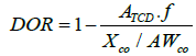
ATCD [a.u./g] is the area resulting from the integration of the TCD signal for the Co-catalyst normalized per mass catalyst; f [moles of H2/a.u.] is a calibration factor correlating the area of the TCD signal and the H2 consumed for the Ag2O standard; XCo is the mass fraction of cobalt in the catalyst sample and AWCo is the atomic weight of Co (58.9 g/mol).
The cobalt dispersion (D,%) and the cobalt crystallite size (d(Co°), nm), were calculated by hydrogen static chemisorption on the reduced catalysts. The measurements were performed on a Micromeritics ASAP 202°C unit at 35°C. A complete description of the sample preparation, procedure and instrument analysis for the materials characterization can be found in our previous work [36].
Catalytic testing
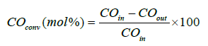
Fischer–Tropsch experiments were performed in a stainlesssteel fixed-bed reactor at process conditions: 210°C, 20 bar, molar H2/CO ratio=2:1. A mixture of 1 g of catalyst with a pellet size between 53–90 μm was diluted and mixed with 5 g of SiC in order to achieve an even temperature profile and was thereafter placed in the reactor [36]. Prior to the reaction the catalyst was activated by reducing it in situ with hydrogen at 350°C for 16 h at atmospheric pressure. The catalysts were tested in two periods, first a syngas flow of 100 Ncm3/min (NTP) for 25 h of Time of Stream (TOS) and thereafter, in the second period the gas flow was changed in order to obtain CO conversion of 30% [33,35,37,38]. The heavy Hydrocarbons (HCs) and most of the water were condensed in two traps kept at 120°C and room-temperature, respectively. The product gases leaving the traps were depressurized and analyzed on-line with an Agilent 6890 Gas Chromatograph (GC) equipped with a Thermal Conductivity Detector (TCD) and a Flame Ionization Detector (FID). H2, N2, CO, CH4, and CO2 were separated by a Carbosieve II packed column and analyzed on the TCD. The percentage of CO conversion was calculated by:
C1–C6 products were accurately separated by an alumina PLOT column and quantified on the FID detector. From which it was possible to determine the C5+ selectivity (SC5+) which is a widely used measure for long-chain hydrocarbons selectivity. The SC5+, if excluding CO2 from the C-atom balance, is defined as follows [35,39]:

Results and Discussion
Synthesis approach
The silatrane formation: For the first time, a generalized synthesis strategy for the preparation of mesoporous materials with 1D, 2D and 3D structures using the atrane route is presented in this study. The silatrane complex was obtained by fully deprotonated triethanolamine-like species as ligands [21,27]. The (TEAH3) triethanolamine N(CH2-CH2–OH)3 reacts with tetraortosilicate Si(OC2H5)4) and replaces the four alcohols from the TEOS forming a stable amine-trialkoxo-complexes by acting (tetradentate) tripod ligand (Figure 1) [21,40].
MCM-41 and PE-MCM-41 silica formation: Once the silatrane were formed, water addition promotes their consequent hydrolysis processes (thermodynamically favored). Even at basic medium the hydrolysis process is delay due to the formed metal-complex i.e., silatrane. Due the steric effect of the ligands in the silatrane complex (Figure 1), the OH- groups have difficulties to reach the metal “Si”. Consequently the hydrolysis is slow, and subsequently the silica polymerization also slows down. The final formed oligomers has a negative charge density due to the ethanol elimination from the atrane complex, at the same time the cationic surfactant (CTA+Br-), is formed in micellar aggregates of CTA+ which can match with negatively charged oligomers by strong electrostatic interaction and form silica coated surfactant micelles [23].
Self-assembly of surfactant micelles and swelling agent: The CTAB has a positive charged polar head group and a large alkyl chain as a non-polar group. The CTAB micelles tend to form an ellipsoid shape in aqueous solution with the hydrophilic head groups and condensed counter ions being considered as an electron dense shell around the core formed by the hydrophobic tails. Depending on the CTAB concentration, it might form hexagonal mesotructures with 1D channel structure, structure that the silica will adopt after surfactant removal i.e., MCM-41. In the case of PE-MCM-41, the swelling agent TIPB self-organize inside the array channels formed with CTA+ into concentric cylinders, expanding in this way the micelle diameter [41,42].
SBA-15 and PE-SBA-15 silica formation: The surfactant P123 used for the SBA-15 synthesis is a mixture of a triblock copolymer: Polyethylene oxide/polypropylene oxide/polyethylene oxide (EO/PO/EO). The EO block is hydrophilic and the PO block is hydrophobic [43]. The micellization of the triblock copolymers is driven by the hydrophobic Polyethylene Oxide (PO) block with a core consisting of PO blocks and a corona of EO blocks [44-46]. The hydrophilic part EO will attract the anionic oxo-hydroxo- Si oligomers forming in this way the inorganic siliceous condensation on the micelles. When the TMB is added to the synthesis, it prefers to self- assemble in the hydrophobic core of PO, causing the micelles to swell. Finally, the addition of the swelling agent (TMB) might affect the surfactant micelles equilibrium formation and produce disorganized materials as it was reported somewhere else [47,48]. For this reason we suggest to use a silatrane complex, as metal precursors of Si. In addition, the synthesis of pore-expanded silicas in our case was performed at soft conditions, while other methods proposed the use of an autoclave in a post synthesis process.
Materials characterization
Chemical composition and particle size analysis (X-ray diffraction): X-ray diffraction patterns measured at angles (2θ=10–80°) did not show any peak for the supports, showing the absence of crystalline domains, thereafter are not presented in this work Table 2 and Figure 2 show the results for the cobalt catalysts from the XRD diffractograms. Co3O4 species are identified for all the catalysts. From the (3 1 1) Co3O4 peak located at 2θ=36.9°, the average particle size using Scherrer's equation was calculated in Table 2. The calculated particle size value for Co3O4 was converted to Co°. Results show that Co3O4 particles increase with the support pore diameter. Obtaining the smallest Co3O4 particle size for Co/MCM-41. Co/PE-SBA-15 and Co/SBA-15 shows almost the same cobalt oxide average particle size.
| Sample | BET Surface area (m2/g) | Total pore volumea (cm3/g) | Mesopore diameterb (nm) |
|---|---|---|---|
| MCM-41 | 1200 | 0.9 | 2.6 |
| PE-MCM-41 | 900 | 1.8 | 6.3 |
| SBA-15 | 940 | 1.1 | 7.5 |
| PE-SBA-15 | 860 | 1.9 | 29.3*/5.0 |
| Co/MCM-41 | 990 | 0.8 | 3.1 |
| Co/PE-MCM-41 | 633 | 1.4 | 6.8 |
| Co/SBA-15 | 721 | 0.8 | 7.9 |
| Co/PE-SBA-15 | 576 | 1.8 | 29.0*/7.1 |
Table 1: Textural properties of the supports and catalysts by N2-adsorption (aDetermined from a single point of adsorption at P/P0=0.998; bEstimated by BJH formalism (desorption branch); *The two values represent the cell diameter and window diameter of the cell from BJH adsorption and desorption).
| Sample | XRD | H2-Chemisorption | ||||
|---|---|---|---|---|---|---|
| d(Co3O4)a (nm) | d(Co°)b (nm) | d(Co°)cH (nm) | Dd (%) | Decorr (%) | DORf (%) | |
| Co/MCM-41 | 7.0 | 5.3 | 4.7 | 7.2 | 7.1 | 35 |
| Co/PEMCM-41 | 9.4 | 7.0 | 6.1 | 6.8 | 5.6 | 43 |
| Co/SBA-15 | 15.1 | 11.3 | 7.2 | 8.0 | 8.0 | 60 |
| Co/PESBA-15 | 14.7 | 11.1 | 7.5 | 7.4 | 7.4 | 58 |
Table 2: Physicochemical characteristics (aCalculated from Scherrer equation; bAccording with: d(Co°)= 0.75·d(Co3O4); CParticle size calculated after reduction at 350°C for 16 h in H2; dMetal dispersion, after reduction at 350°C for 16 h in H2; eDispersion corrected by DOR According to: d(Co°)  ; fDegree of reduction from TPR of reduced catalysts).

Figure 2: X-ray patterns for the studied catalysts calcined at 550°C.
Textural properties: The textural properties of the supports and cobalt catalysts are listed in Table 1. The N2 adsorption-desorption isotherms and pore size distribution of all the silica supports according to the Barrett–Joyner–Halenda (BJH) method [47] are shown in Figure 3. According to the IUPAC nomenclature, all the catalysts have type IV (a) isotherms corresponding to mesoporous adsorbents with a pore diameter in the range of 2–50 nm [48,49].

Figure 3: The N2 sorption isotherms and pore size distribution curves for the mesoporous silica supports.
Both MCM-41 and SBA-15 silicas (Figure 3) present narrow pore size distribution, SBA-15 has almost twice the average pore diameter size of MCM-41 silica (Table 1). PE-MCM-41 presents a particular physisorption isotherm with two hysteresis, the first one for P/PO=0.45–0.8 related to the N2 condensation inside the cylindrical pores of the material as in the case of MCM-41; the second small hysteresis loop at P/PO=0.90–0.95 is ascribed to N2 condensation in the inter-particle pores with a pore size distribution at 30 nm. Consequently it is assumed that this material has structural and textural porosity.
The hysteresis for PE-SBA-15 in Figure 3 presents a type H2(b) loop associated with pore blocking, this type of hysteresis loops describes a 3D cell structure with interconnected pores (windows) [49]. The cell diameter and the window diameter are obtained from the adsorption and desorption branches of the isotherms respectively (Figure 3 and Table 1).
Both, the BET surface area and total pore volume of the supports after cobalt deposition decrease, and the average pore size increase (Table 2). The explanation given for this fact is that the smaller pores plugging by cobalt oxide particles makes them inaccessible to N2 (adsorbate) molecules and thus decreases the surface area and pore volume while the pore size results bigger [50].
Scanning and transmission electron microscopies: Representative SEM images of MCM-41, PE-MCM-41, SBA-15 and PE-SBA-15 are illustrated in Figure 4. MCM-41 shows a perfect hexagonal structure extrapolated from its nano- scale structure. SBA-15 presents fiber-like morphologies of different sizes and widths [51]. The morphology from the initial MCM-41 and SBA-15 was changed from hexagonal and cylindrical tubes to agglomerated spherical particles. This result was produced by the addition of the swelling agent; and suggests that the swelling agent is not only inside the CTAB and P123 micelles, but also outside, which can prevent the formation of big and long particles.

Figure 4: Representative SEM images of a) MCM-41, b) PE-MCM-41, c) SBA-15 and d) PE-SBA-15 calcined at 550°C for 6 h.
The morphology of the supports did not changed after cobalt deposition; thereafter the SEM pictures are not presented in this work.
Further studies from the TEM images in Figure 5 showed that Co/ MCM-41, Co/PE-MCM-41 and Co/SBA-15 have channel structures with different pore sizes. Here it is evident that PE-MCM-41 preserved the channels from MCM-41 silica, but changed the 1D channel formation to 2D channels with perpendicular direction. PE-SBA-15 changed the mesostructure to a 3D mesocellular foam shape. This is in agreement with N2 adsorption-desorption results. Cobalt particles were also identified in Figure 5 (A1 and A2). Due to differences in electronic density, the areas of darker contrast were assigned to cobalt oxide whilst the areas of lighter contrast were due to the silica support. Co/MCM-41 presented a well-organized pore structure of the support with agglomerated cobalt oxide particles mostly outside de pores (Figure 5). The cobalt oxide seems to be more dispersed inside the pores in Co/PE-MCM- 41 (Figure 5 (B2)). On the other side a homogeneous dispersion and particle size of Co3O4 are seen in Co/SBA-15. Co/PE-SBA-15 shows the 3D mesocellular foam pore structure of the silica. The network was formed for pore cells with a main pore diameter of 30 nm and interconnected windows (Figure 5 (D2)). Additionally this material showed big agglomerations of cobalt oxide, but also particles inside the spherical pores (Figure 5 (D1)). In all the cases Co3O4 particles seems to be formed on both the external and internal surface of the materials which are comparable with other researches [52].

Figure 5: Representative TEM images of A) Co/MCM-41, B) Co/PE-MCM-41, C) Co/SBA-15, D) Co/PE-SBA-15 after cobalt deposition calcined at 350°C for 10 h. The letters with number 2 shows higher resolution of catalysts.
Physicochemical analysis: H2-Temperature Programmed Reduction: A comparison of the reduction temperature profiles for the final catalysts are shown in Figure 6. Unsupported as well as supported cobalt oxide Co3O4 is reduced in two steps: one (Co3O4 + H2→ 3CoO + H2O) and the second step (3CoO + 3H2 → 3CoO + 3H2O). The last one is more sensitive to the support, particle size, particle-support interaction, reductant flow (rate and composition) and heating rate. Figure 2 shows two main H2 uptakes for all the catalysts; the first one at temperatures below 500°C corresponding to the reduction of Co3O4 and CoO; the second one at temperatures higher than 500°C correspondent to strong metal support interaction [53-55].
Then, it is concluded that more Co3O4 and less CoO species are present in Co/MCM-41 than in Co/PE-MCM-41, while the Co-silicates species are higher in Co/MCM-41. From these results one can expect that Co/PE-MCM-41 has more reducible cobalt at 350°C, which is required for FTS. These differences are attributed to the higher surface area and small pore diameter size, which favors the formation of very small particles that can easily interact with –OH species present in MCM-41 silica. Co/SBA-15 shows more CoO species than Co3O4 and less cobalt-support species compared with Co/PE-SBA-15. Cobalt-support interaction in Co/PE-SBA-15 is attributed to the more open network of the silica support which favors the diffusion of Co ions during impregnation and calcination. Thereafter these cobalt ions might reach the window pores in the cell spheres where the probability of interact with the silanol groups is higher due the small window pore size.
Co/MCM-41 and Co/SBA-15 catalysts showed very different reduction properties. One explanation might be the pore diameter of the silica support. It was reported that smaller pore diameter in mesoporous silica likely forms and stabilizes smaller cobalt oxide particles with higher dispersion. Nevertheless, the pore diameter of the silica support material is not the only possible explanation for diverse reduction properties. Some authors tried to explain the difference between MCM-41 and SBA-15 and found that the pore surface consists of regularly arranged isolated surface SiOH groups. These OH species in parallel direction to the cylindrical pore axis are absent in MCM-41. On the contrary, the inner surface of SBA-15 contains isolated and interacting SiOH groups able to form hydrogen bonds with other OH groups as well as geminal Si(OH)2 groups with all of them pointing in all directions of space. Pore models have shown that the inner surface of SBA-15 is substantially “rougher” than the pore surface of MCM-41 [56]. Therefore it is reasonable to think that due to the rougher inner surface of the SBA-15 support, the interactions of cobalt particles with silica surface sites in the Co/SBA-15 catalyst are weaker and as a result less cobalt-silicate is formed.
The Co° particle size and dispersion is calculated from H2- chemisorption after catalyst activation and reported in Table 2. This technique showed similar Co° particle sizes compared with XRD analysis. Co/SBA-15 showed the highest dispersion. These result could be attributed to the weak Co–silicate interaction caused by the presence of interconnected 2D pores and the pores inner surface discussed previously [56]. Consequently, the Degree of Reduction (DOR) is higher for Co/SBA-15. It is interesting to note that the degree of reduction is also high for Co/PE-SBA-15 even though it has a high cobalt-silicate formation. The explanation given to this fact is the pore structure and size of the silica. It was reported that water produced during reduction process oxidizes the Co°, effect that is more pronounced in catalysts with small and long pores due to water accumulation inside the pores [11]; however this is not the case for the PE-SBA-15 which has large 3D spherical pores and the produced water is more easy to diffuse through this network and possibly might be less Co° oxidation, which can favor the degree of reduction.
Catalytic activity
As explained in the experimental part, the tests consisted of two periods. In the first period, the catalysts were tested at a Gas Hourly Space Velocity (GHSV) of 6000 ml/h-gcatalyst (NTP) in order to compare the CO conversion. In the second period the GHSV was adjusted in order to operate at CO conversion of 30 ± 4%. The GHSV employed during each period and the corresponding average CO conversions are presented in Table 3.
| GHSV | Catalysts | XCO (%) | SCH4a (%) | SC5+a (%) | SCO2 (%) |
|---|---|---|---|---|---|
| 6000 | Co/MCM-41 | 4.4 | 12.2 | 76.3 | 1.4 |
| 1500 | 27.0 | 8.6 | 83.5 | 1.0 | |
| 6000 | Co/PE-MCM-41 | 5.7 | 10.1 | 80.0 | 0.7 |
| 1600 | 29.1 | 8.7 | 84.6 | 0.4 | |
| 6000 | Co/SBA-15 | 10.0 | 18.1 | 62.3 | 2.2 |
| 2550 | 28.0 | 13.6 | 74.4 | 1.8 | |
| 6000 | Co/PE-SBA-15 | 18.5 | 11.1 | 73.6 | 1.2 |
| 4800 | 28.5 | 7.2 | 85.2 | 0.8 |
Table 3: Conversion levels and selectivity data for the different catalysts (aSelectivities are CO2-free).
As can be deduced by comparing CO conversions during the first period, the catalyst activity decreases in the following order: Co/PE-SBA-15>Co/SBA-15>Co/PE-MCM-41>Co/MCM-41. By the physicochemical characterization, it was deducted that our best candidates for the Fischer-Tropsch reaction was Co/SBA-15 and Co/PE-SBA-15. Both catalysts had similar cobalt particle size, degree of reduction and dispersion; however the catalytic results showed almost double CO conversion for Co/PE-SBA-15 (Table 3). Hereafter, the catalytic result is attributed mainly to the pore structure and average pore diameter. The presence of 3D pores with spherical shape and pore windows might favor the reactants and products diffusion. While in the 1D and 2D pores (Co/MCM- 41, Co/SBA-15 and Co/PE-MCM-41) are more limited.
Lower CO conversion for Co/MCM-41 was observed, as expected from the physicochemical characterization. It can be related to the low availability of active cobalt on the catalyst surface, due to the high formation of Co-silicates, which are easier to form when a high surface area is present, due to the presence of more -OH species and disposition inside the pores.
Furthermore, Table 3 shows a comparison of the product selectivities during the second period at around 30 % of CO conversion. In general, the selectivity to hydrocarbons with a carbon chain longer than five carbon atoms (SC5+) increases at higher CO conversion. This effect is usually ascribed to a higher extent of secondary reaction (α-olefin re-adsorption) and/or the effect of a higher partial pressure of the water formed during FT reaction [17,57]. As the selectivity of C5+ increases with CO conversion, the selectivity to CH4 is then reduced. However, the selectivity to C5+ decreases in the order: Co/PE-SBA-15>Co/SBA- 15>Co/PE-MCM-41>Co/MCM-41. This might be attributed to the small pore size of the supports with channel structure i.e. MCM-41, SBA-15 and PE-MCM-41 where H2 difuses faster than CO due to molecular size. This leads to higher H2/ CO ratios within the catalyst channels, and a higher H2/CO ratio promotes the selectivity to methane and short hydrocarbon chains. In the case of Co/PE-SBA-15 that has cell spheres structures this gradient of H2/CO is limited and the intermediate hydrocarbon chains are not easily hydrogenated. The selectivity to CO2 is low for all the catalysts and decreases at higher CO conversions due to water gas shift reactions due to the water production at FTS [24].

Figure 6: H2 TPR profiles of the cobalt catalysts calcined at 350 °C for 10 h. (MSI = metal-support interaction).
Conclusion
Mesoporous silicas with structure type MCM-41, SBA-15 and their correspondent pore-expanded PE-MCM-41 and PE-SBA-15 were synthetized by the atrane route and used as supports for cobalt Fischer-Tropsch catalysts. The atrane route allowed the synthesis of homogeneous materials with tunable pore diameter and narrow pore size distribution at soft conditions. The final silica materials had 1D, 2D and 3D structures. The particle size of the deposited cobalt oxide on these materials was influenced by the support pore size. Higher degree of reduction was found for larger Co0 particles on Co/SBA-15 and Co/PE-SBA-15, which resulted in more catalytic active sites. However, Co/PE-SBA-15 catalyst showed better catalytic results in terms of CO conversion and selectivity to hydrocarbons with chains longer than 5 carbon atoms. Such a good results were attributed to the 3D pore structure and pore size of the silica which favored the reactants and products diffusion.
Acknowledgments
Swedish International Development Cooperation Agency (SIDA), Nanoandes network and European project COST action: CM0903 are thanked for financial support. Special thanks to Gustavo García (Luleå University) for SEM pictures.
References
- Schüth F, Wingen A, Sauer J (2001) Oxide loaded ordered mesoporous oxides for catalytic applications. Microporous Mesoporous Mater 44–45: 465-476.
- Li Z, Wu J, Yu J, Han D, Wu L, et al. (2016) Effect of incorporation manner of Zr on the Co/SBA-15 catalyst for the Fischer–Tropsch synthesis. J Mol Catal A Chem 424: 384-392.
- Shimizu T, Ushiki I, Ota M, Sato Y, Koizumi N, et al. (2015) Preparation of mesoporous silica supported cobalt catalysts using supercritical fluids for Fischer–Tropsch synthesisChem Eng Res Des 95: 64-68.
- Tüysüz H, Schüth F (2012) Ordered Mesoporous Materials as Catalysts. Adv Catal 55: 127-239.
- Van de Loosdrecht J, Botes FG, Ciobica IM, Ferreira AC, Gibson P, et al. (2013) Fischer-Tropsch synthesis: catalysts and chemistry. Elsevier pp: 525-557.
- Grenoble DC, Estadt MM, Ollis DF (1981) The chemistry and catalysis of the water gas shift reaction: 1. The kinetics over supported metal catalysts. J Catal 67: 90-102.
- Dry ME (2002) The Fischer–Tropsch process: 1950–2000. Catalysis Today 71: 227- 241.
- Suárez París R, Lopez L, Barrientos J, Pardo F, Boutonnet M, et al. (2015) Catalytic conversion of biomass-derived synthesis gas to fuels. The Royal Society of Chemistry 27: 62-143.
- Azzam K, Jacobs G, Ma W, Davis BH (2014) Effect of cobalt particle size on the catalyst intrinsic activity for fischer-tropsch synthesis. Catal Letters 144: 389-394.
- Bechara R, Balloy D, Dauphin JY, Grimblot J (1999) Influence of the Characteristics of γ-Aluminas on the Dispersion and the Reducibility of Supported Cobalt Catalysts. Chem Mater 11: 1703-1711.
- Dalai AK, Davis BH (2008) Fischer–Tropsch synthesis: A review of water effects on the performances of unsupported and supported Co catalysts. Appl Catal A: Gen 348: 1-15.
- Iglesia E (1997) Fischer-tropsch synthesis on cobalt catalysts: Structural requirements and reaction pathways. Stud Surf Sci Catal 153-162.
- Khodakov AY, Bechara R, Griboval-Constant A (2002) Structure and catalytic performance of cobalt Fischer Tropsch catalysts supported by periodic mesoporous silicas Stud Surf Sci Catal 142: 1133-1140.
- van Steen E, Claeys M, Dry ME, van de Loosdrecht J, Viljoen EL, et al. (2005) Stability of nanocrystals: Thermodynamic analysis of oxidation and re- reduction of cobalt in water/hydrogen mixtures. J Phys Chem B 109: 3575-3577.
- Wei L, Zhao Y, Zhang Y, Liu C, Hong J, et al. (2016) Fischer–Tropsch synthesis over a 3D foamed MCF silica support: Toward a more open porous network of cobalt catalysts. J Catal 340: 205-218.
- Jung JS, Kim SW, Moon DJ (2012) Fischer–Tropsch Synthesis over cobalt based catalyst supported on different mesoporous silica. Catal Today 185: 168-174.
- Ghampson IT, Newman C, Kong L, Pier E, Hurley KD, et al.(2010) Effects of pore diameter on particle size, phase, and turnover frequency in mesoporous silica supported cobalt Fischer–Tropsch catalysts. Appl Catal A: Gen 388: 57-67.
- Saib AM, Claeys M, Van Steen E (2002) Silica supported cobalt Fischer–Tropsch catalysts: effect of pore diameter of support. Catal Today 71: 395-402.
- Xiong H, Zhang Y, Liew K, Li J (2008) Fischer–Tropsch synthesis: The role of pore size for Co/SBA-15 catalysts. J Mol Catal B Enzym 295: 68-76.
- Kruk M, Jaroniec M, Ryoo R, Joo SH (2000) Characterization of MCM-48 silicas with tailored pore sizes synthesized via a highly efficient procedure. Chem Mater 12: 1414-1421.
- Cabrera S, Haskouri JE, Alamo J, Beltrán A, Beltrán D, et al. (1999) Surfactant-assisted synthesis of mesoporous alumina showing continuously adjustable pore sizes. Adv Mater 11: 379-381.
- Cabrera S, Haskouri JEI, Guillem C, Latorre J, Beltrán-Porter A, et al. (2000) Generalised syntheses of ordered mesoporous oxides: the atrane route. Solid State Sci 2: 405-420.
- de Zárate DO, Fernández L, Beltrán A, Guillem C, Latorre J, et al. (2008) Expanding the atrane route: Generalized surfactant-free synthesis of mesoporous nanoparticulated xerogels. Solid State Sci 10: 587-601.
- Rytter E, Tsakoumis NE, Holmen A (2016) On the selectivity to higher hydrocarbons in Co-based Fischer–Tropsch synthesis. Catal Today 261: 3-16
- El Haskouri J, Cabrera S, Guillem C, Latorre J, Beltrán A, et al. (2002) Atrane precursors in the one-pot surfactant-assisted synthesis of high zirconium content porous silicas. Chem Mater 14: 5015-5022.
- Cabrera MS (1999) Química en medios organizados para la obtención de nuevas alúminas aluminosilicatos y ALPOs mesoporosos con tamaño de poro modulable, instituto Universitario de Ciencia de los Materiales, Universitat de Valencia: Valencia Spain.
- El Haskouri J, Cabrera S, Caldés M, Alamo J, Beltran-Porter A, et al. (2001) Ordered mesoporous materials: composition and topology control through chemistry. Int J Inorganic Mater 3: 1157-1163.
- Garcia PRAF, Bicev RN, Oliveira CLP, Sant’Anna OA, Fantini MCA (2016) Protein encapsulation in SBA-15 with expanded pores. Microporous Mesoporous Mater 235: 59-68.
- Sprague M J (1985) Characterization of heterogeneous catalysts. Chemie Ingenieur Technik 57: 430-430.
- Delannay F (1984) Characterization of Heterogeneous Catalysts.
- Schanke D, Vada S, Blekkan EA, Hilmen AM, Hoff A, et al. (1995) Study of Pt-promoted cobalt CO hydrogenation catalysts. J Catal 156: 85-95.
- Bhatia S, Beltramini J, Do DD (1990) Temperature programmed analysis and its applications in catalytic systems, Catal Today 7: 309-438.
- Borg Ø, Eri S, Blekkan EA, Storsæter S, Wigum H, et al. (2007) Fischer–Tropsch synthesis over γ-alumina-supported cobalt catalysts: effect of support variables. J Catal 248: 89-100.
- Tristantini D, Lögdberg S, Gevert B, Borg Ø, Holmen A (2007) The effect of synthesis gas composition on the Fischer–Tropsch synthesis over Co/γ-Al2O3 and Co–Re/γ-Al2O3 catalysts. Fuel Processing Technology 88: 643-649.
- Lualdi M, Lögdberg S, Regali F, Boutonnet M, Järås S (2011) Investigation of mixtures of a Co-based catalyst and a Cu-based catalyst for the Fischer–Tropsch synthesis with bio-syngas: the importance of indigenous water. Top Catal 54: 977-985.
- Pardo-Tarifa F (2017) Ce-promoted Co/Al2O3 catalysts for Fischer–Tropsch synthesis. Int J Hydrogen Energy.
- Storsæter S, Borg Ø, Blekkan EA, Holmen A (2005) Study of the effect of water on Fischer–Tropsch synthesis over supported cobalt catalysts. J Catal 231: 405-419.
- Lualdi M (2012) Fischer-Tropsch Synthesis over Cobalt-based Catalysts for BTL Applications. KTH Royal Institute of Technology, Sweden.
- Lögdberg S, Lualdi M, Järås S, Walmsley JC, Blekkan EA, et al. (2010) On the selectivity of cobalt-based Fischer–Tropsch catalysts: evidence for a common precursor for methane and long-chain hydrocarbons. J Catal 274: 84-98.
- Kondratenko Y, Fundamensky V, Ignatyev I, Zolotarev AA, Kochina T, et al. (2017) Synthesis and crystal structure of two zinc-containing complexes of triethanolamine. Polyhedron.
- Sayari A, Yang Y, Kruk M, Jaroniec M (1999) Expanding the pore size of MCM-41 silicas: use of amines as expanders in direct synthesis and postsynthesis procedures. J Phys Chem B 103: 3651-3658.
- Sayari A, Shee D, Al-Yassir N, Yang Y (2010) Catalysis over pore-expanded MCM-41 mesoporous materials. Top Catal 53: 154-167.
- https://ace-notebook.com/bandgap-measurements-of-low-k-porous-organosilicate-free-related-pdf.html
- Bartolini M, Molina J, Alvarez J, Goldwasser M (2015) Effect of the porous structure of the support on hydrocarbon distribution in the Fischer–Tropsch reaction. J Power Sources 285: 1-11.
- Sanz R, Calleja G, Arencibia A, Sanz-Pérez ES (2015) CO 2 capture with pore-expanded MCM-41 silica modified with amino groups by double functionalization. Microporous Mesoporous Mater 209: 165-171.
- Sanz R, Calleja G, Arencibia A, Sanz-PeÃŒÂÂrez ES (2013) CO2 uptake and adsorption kinetics of pore-expanded SBA-15 double-functionalized with amino groups. Energy, Fuels 27: 7637-7644.
- Barrett EP, Joyner LG, Halenda PP (1951) The determination of pore volume and area distributions in porous substances, I, Computations from nitrogen isotherms. J Am Chem Soc 73: 373-380.
- Brunauer S, Deming LS, Deming WE, Teller E (1940) On a theory of the van der Waals adsorption of gases. J Am Chem Soc 62: 1723-1732.
- Thommes M, Kaneko K, Neimark AV, Olivier JP, Rodriguez-Reinoso F, et al. (2015) Physisorption of gases with special reference to the evaluation of surface area and pore size distribution (IUPAC Technical Report). Pure Appl Chem 87: 1051-1069.
- Martínez A, Prieto G, Rollán J (2009) Nanofibrous γ-Al2O3 as support for Co-based Fischer–Tropsch catalysts: pondering the relevance of diffusional and dispersion effects on catalytic performance. J Catal 263: 292-305.
- Lin HP, Tang CY, Lin CY (2002) Detailed structural characterizations of sbaâ€ÂÂ15 and mcmâ€ÂÂ41 mesoporous silicas on a highâ€ÂÂresolution transmission electron microscope. J Chinese Chem Soc 49: 981-988.
- Taghavimoghaddam J, Knowles GP, Chaffee AL (2013) Impact of preparation methods on SBA-15 supported low cobalt-content composites: structure and catalytic activity. J Mol Catal B Enzym 377: 115-122.
- Topsøe NY, Topsøe H (1982) Adsorption studies on hydrodesulfurization catalysts: I, Infrared and volumetric study of NO adsorption on alumina-supported Co Mo and Co-Mo catalysts in their calcined state. J Catal 75: 354-374.
- Simionato M, Assaf EM (2003) Preparation and characterization of alumina-supported Co and Ag/Co catalysts. Mater Res 6: 535-539.
- Van de Loosdrecht J, Van der Haar M, Van der Kraan AM, Van Dillen AJ, Geus JW (1997) Preparation and properties of supported cobalt catalysts for Fischer-Tropsch synthesis. Appl Catal A: Gen 150: 365-376.
- Hukkamäki J, Suvanto S, Suvanto M, Pakkanen TT (2004) Influence of the pore structure of MCM-41 and SBA-15 silica fibers on atomic layer chemical vapor deposition of cobalt carbonyl. Langmuir 20: 10288-10295.
- González O, Pérez H, Navarro P, Almeida LC, Pacheco JG, et al. (2009) Use of different mesostructured materials based on silica as cobalt supports for the Fischer–Tropsch synthesis. Catal Today 148: 140-147.
Open Access Journals
- Aquaculture & Veterinary Science
- Chemistry & Chemical Sciences
- Clinical Sciences
- Engineering
- General Science
- Genetics & Molecular Biology
- Health Care & Nursing
- Immunology & Microbiology
- Materials Science
- Mathematics & Physics
- Medical Sciences
- Neurology & Psychiatry
- Oncology & Cancer Science
- Pharmaceutical Sciences