The Role of Orthotics in Diabetic Feet: A SurgeonÃÆâÃâââ¬Ãâââ¢s Perspective (Experts Comments)
Andrea Veljkovic1*, Alastair Younger1, Kevin Wing1, Jeff Nacht1, Murray Penner1 and Peter Salat2
1St. Paul’s Hospital, Division of Distal Extremities, Department of Orthopaedics, University of British Columbia, Canada
2Department of Radiology, University of Calgary, Foothills Medical Centre, Calgary, Canada
- *Corresponding Author:
- Andrea Veljkovic
St. Paul’s Hospital
Division of Distal Extremities
Department of Orthopaedics
University of British Columbia
1000-1200 Burrard Street
Vancouver, BC V6Z 2C7, Canada
Tel: (778) 379-7771
E-mail: docveljkovic@yahoo.com
Received date: December 02, 2016; Accepted date: January 31, 2017; Published date: February 07, 2017
Citation: Veljkovic A (2017) The Role of Orthotics in Diabetic Feet: A Surgeon’s Perspective (Experts Comments). Pro Ort Open J 1: 4.
Copyright: © 2017 Veljkovic A, et al. This is an open-access article distributed under the terms of the Creative Commons Attribution License, which permits unrestricted use, distribution, and reproduction in any medium, provided the original author and source are credited.
Keywords
Biomechanics; Orthoses; Lower limbs; Modeling; Boundary element method; Finite element method; Unloading; Personalization
Introduction
Despite the growing use of orthoses in clinic, sports and everyday life, and availability of a number of medical guides and atlases for orthoses [1,2] the line of activity, involving mechanical and mathematical modeling of "Leg-Orthosis" system, is as yet only at the beginning of its development. Publications relating to modeling limbs orthotics per se (biomechanics of foot and insoles constitutes actually a separate independent area of research) by methods of solid mechanics, are isolated yet, and they relate only to orthosis itself and completely ignore the very limb and its mechanical properties [3-5].
At the same time such studies are needed to resolve a number of important issues. For example, it is known that the rate of tissue regeneration depends on the loading level and program [6]. It is therefore important to find out whether it is possible to control the limb unloading in an orthosis – for example, through a change in the orthosis lateral compression, etc [7-9].
In a minimal basic biomechanical model of a shin-orthosis system has been proposed.
This model is pretty coarse, so two more accurate models, developing it, are discussed below: generalized typified model and personalized model [7].
Typified conical model
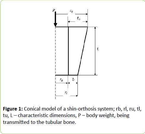
Formulated and based on the boundary integral equation method considered was the problem of modeling of the lower limb by elastic isotropic double truncated cone (muscles) with a rigid cylindrical core (tubular bone), the foot is placed into a rigid shin-conformal cone (orthosis) and loaded with the body weight (Figure 1).
Figure 1: Conical model of a shin-orthosis system; rb, rl, ru, tl, tu, L – characteristic dimensions, P – body weight, being transmitted to the tubular bone.
The muscular layer is engaged with the bone, the body weight is applied to the bone, and is transmitted to the muscles through the bone-muscle interface.
Fields of stresses and displacements are defined numerically by the method of boundary elements. Assuming that the load and the calculation region show an axial symmetry, the boundary integral equations for a three-dimensional elasticity problem are written down in cylindrical coordinates with respect to two variables on the boundary (axial and radial displacement and corresponding force).
The calculation is carried out using the software package that implements the boundary element method with a quadratic approximation of the variables of the problem [10].
Given the data [11-13] the shear modulus for the muscle tissue was taken to be Gm ≅ 2.43 × 10⁴ Pa, which corresponds to the muscles in the active (tense) state, the Poisson's ratio ν=0.5.
The results of calculations
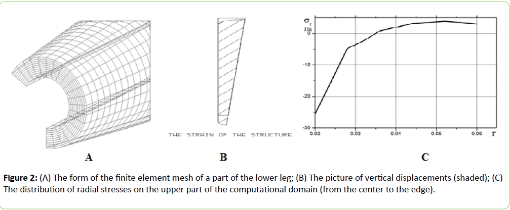
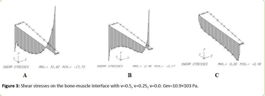
Figures 2 and 3 present some results of calculations on the condition that the vertical (axial to z) displacements Uz are setted Uz= - 0.00001 m under the assumption of complete slippage on the shin-orthosis border. Unless otherwise indicated, variables having the dimension of length, are given in meters in all Figures, stresses – in Pa.
Interesting appeared the results of calculations of shear stresses at the interface of the conical elastic layer and the rigid cylindrical core. Upon initial calculation for ν=0.5 obtained was unexpected and rather complex graph (Figure 3A) with nonmonotonic change in stress along the axis and even with a change in sign. It has been suggested that this effect may be associated with mutual influence of axial and radial components of the tensors of stresses and strains. Similar calculations performed for ν=0.25 (Figure 3B) and ν=0.0 (Figure 3C) with the same value of Gm, confirmed that assumption.
The effect of lateral compression on unloading is of special interest at orthotics since, according to modern concepts [6], bone regeneration (and hence the rate of bone union) depends on current loads (or, more generally, on the loading program).
As explained in Refs. [7,8] lateral compression can significantly affect limb unloading only in the case when full slip mode between the limb and the orthosis is realized.
In reality, the conditions of contact between foot and orthosis correspond neither complete adhesion, nor ideal slippage - it is rather the conditions of dry friction (Coulomb-Mor law), which, depending on the values of the coefficient of friction, mechanical and geometric characteristics of the contacting bodies, as well as operating loads can lead to the formation of sites of both adhesion and slip of different sizes (we note in passing that for reasons of hygiene under the orthosis on the leg stockings are put on, usually cotton).
For a rough initial estimate of the conditions for the occurrence of general slippage the problem was considered under the assumption of full adhesion on the shin-orthosis border.
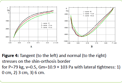
Figure 4 A,B shows the distribution of the boundary σ, τ assuming full adhesion on the shin-orthosis border. The narrow (lower, more stressed) end of the lower leg is on the left, the wide upper end - on the right. Initial growth of normal stresses in the direction of the narrow end is due to the increasing constraint and the subsequent decrease - with the approach of the free edge and decreasing tightness.
Shear stresses: loading with body weight leads to forced displacement of the rigid central part of the cone (bone) down.
Since the side boundaries of the lower narrow part of the cone are closer to the axis, material on the lower part of the boundary is dragged in and moves in the same direction as the axial part, wiile in the lower part, a strong compression rises, so that the material begins to be squeezed up along the lateral boundaries to the free upper part and moves in the opposite direction, which is accompanied by a change of sign of the tangential stresses.
With increasing tightness (and consequently decreasing the taper angle and the cone shape approach to the cylinder), the region of sign change of tangential stresses is shrinking, and the maximum of the normal stresses shifts slightly towards the center.
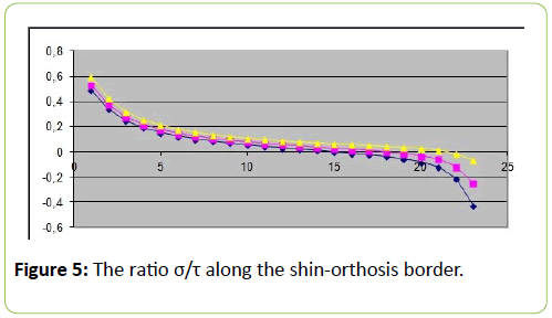
At dry friction by Coulomb's law relation τ ≤ kσ must hold on the contact surface, where τ and σ stands respectively for the tangential and normal stresses at the Shin-Orthosis border. For the problem with full adhesion the ratio σ/τ along the shinorthosis border is given by Figure 5.
It is seen that in order to begin sliding portions arising on the contact surface, it is necessary that the friction coefficient k be less than about 0.5. With increasing tightness the sliding area size at the top of the shin (left end in Figure 5) is reduced, and at the bottom (right end in Figure 5) increases.
For a more precise determination of the conditions of full slip occurrence calculations are currently underway for cone model with direct and explicit assignment of Mohr-Coulomb conditions at the shin-orthosis border.
Experimental research of possibility of unloading control at orthotics by changing the lateral compression are presented in Refs. [7,8], among others note [14].
Personalized model (model of real form)
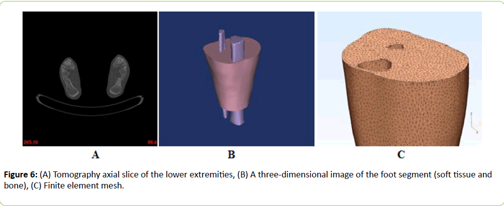
Modeling the shin with combination of cylinders and cones within the axisymmetric models still markedly coarsens the real situation, because the shin and the tibia (which transmits the most of the axial load) are not quite the cones (or cylinders), and the latter also is located not centrally within the lower leg but rests against its front surface. For a more realistic description of the limb and orthosis geometry and further refinement of the model the shin multislice computed tomography (MSCT) in vivo was performed.
The result of tomography is a large set of bitmap files (up to thousands) of DICOM (Digital Imaging and COmmunications in Medicine) format - the industry standard for distribution and viewing of medical images). These image files are pictures of the X-ray density distribution in the sequence of flat sections of the object under study, where each tissue corresponds to its own density range (Figure 6A-C). Transforming bitmaps CT scan into the FEM mesh model is a separate meaningful task for which solution there are a number of specially developed software systems. In this study we used Mimics program [15] one of the most known and powerful systems of this kind.
Based on graphics tomography files and using Mimics software system a three-dimensional image of the feet was created and the corresponding 3D finite element mesh obtained.
The resulting finite element mesh was passed to the FEM software package ABAQUS. In carrying out calculations using finite element method it was assumed that the shin is "suspended" in an orthosis as in a funnel, and is loaded by the weight of the body, which is applied to the bones, and is transmitted to the muscles through the bone-muscles interface. The loading of the bones leads to their drawdown in the vertical direction. It is this vertical sediment that was set in the present study during preliminary calculations. It was assumed [7] that the bones are rigid, shin muscles are elastic and isotropic, sleeve orthosis is conformal to the leg and absolutely rigid. The shear modulus for muscle tissue based on the data [11-13] was assumed to be Gm ≅ (0.77÷2.43) × 104 Pa, where 0.77 corresponds to muscles in passive (relaxed) state, and 2.43 - muscles in the active (tense) state, the Poisson's ratio ν=0.5.
The results of calculations
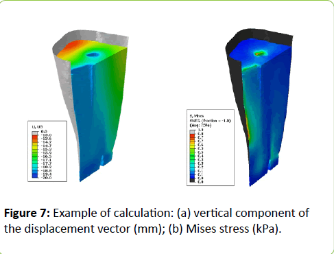
Figure 7A,B shows the results of calculation of the vertical component of the displacement vector and the Mises stress corresponding to the case of relaxed muscles, provided slippage on the shin-orthosis border. The results were obtained by setting the bone vertical subsidence equal to ≈ 18 mm. In the case of strained muscles the picture is qualitatively equivalent to the one shown in Figure 7A,B.
Figure 7: Example of calculation: (a) vertical component of the displacement vector (mm); (b) Mises stress (kPa).
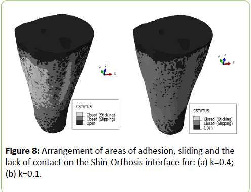
To study the possibility of unloading control at orthotics the same problem was examined under the condition of dry friction with the coefficients of friction equal to 0.4 (cotton stocking) and 0.1 (stocking of slippery synthetics).
The shear modulus for muscle tissue was taken equal to Gm ≅ 24.3 × 10³ Pa, i.e., for shin muscles in the active (tight) state. Figure 8 shows the distribution of areas of seizing (light), sliding (gray) and the lack of contact (dark) with k=0.4 (left) and k=0.1 (right). It can be seen according to the calculations, that while when k=0.4 adhesion mode at the shin-orthosis boundary is realized, at k=0.1 there are no areas of seizing at all (general slip). Thus, one can expect that, in accordance with considerations advanced in Refs. [7,8], when using cotton stocking under an orthosis lateral compression will not affect the unloading due to the lack of sliding, but for slippery synthetic stocking such an effect is possible. However, experiments showed no dependence of unloading on the lateral compression [7,9]. For cotton stocking with k=0.48 this indicates that adhesion limb-orthosis mode is realized (in which unloading is essentially independent on compression). For slippery stockings with k ∼ 0,1 this means, apparently, that despite the possibility of slipping of the leg along the orthosis, the dependence of unloading on lateral compression is blocked by other mechanisms, such as the so-called "piston effect" (skin stretching under a load and its shift-slip along a thin and soft layer of subcutaneous fat).
Conclusions
The technique, developed on the basis of a typed conical model using BEM, enables rapid parametric study of the legorthosis model stress-strain state and getting all of the stressstrain state components distributions. In this case a single BEM calculation using conical model takes a few seconds.
Personalized approach to modeling shin-orthosis system based on the use of the shin computer tomography and FEM analysis allows to take into account the real three-dimensional geometry of the shin, shin-orthosis contact conditions, bones loading conditions and soft tissue properties, maximally close to real. Moreover, the relation between images radiopacity and bone density in accordance with the so-called Hounsfield scale, as well as theoretical and empirical relation between bone density and its Young's modulus [16] allow you to specify in the model the inhomogeneous distribution of the mechanical characteristics of bone (in fact, Young's modulus). However, even after all the necessary operations in Mimics and transferring model into the FE package every single calculation by this method requires several hours on a typical modern computer.
Using stockings under an orthosis with high coefficients of friction to the skin and to the orthosis (e.g., cotton stockings with coefficients of friction k >∼ 0,4) eliminates the possibility of limb unloading control in the orthosis due to changes in the lateral compression, by blocking leg sliding along the orthosis. Slippery stockings (with friction coefficients k∼0.1) provide slippage. This condition, however, is necessary but not sufficient. The fact that in this case, the experiment also shows no significant effect of the lateral compression on unloading, is caused, presumably, by the action of another, so-called "piston" effect (skin stretching under a load and its shift-slip along a thin and soft layer of subcutaneous fat).
It is possible, however, that the goal can be achieved on the basis of more complex schemas with specially created adjustable gaps and tabs-shock absorbers, which will allow both to dose and, coming together with the strain gauges in the sensor unit, to control the load on the limb.
Acknowledgments
This work was supported by RFBR 14-08-01266 and 14-08-00537 grants.
References
- Hsu JD, Michael JW, Fisk JR (2008) AAOS Atlas of Orthoses and Assistive Devices (4th ed.) Mosby-Elsevier, Philadelphia.
- Poitout DG (2004) Biomechanics and Biomaterials in Orthopedics (1st ed.) Springer.
- Creylman V, Vander Sloten J, Vermetten D, Peeraer L (2008) Finite element analysis of ankle foot orthoses. In: Proceedings of the 1st international Foot and Ankle Biomechanics (i-FAB) community Congress p: 137.
- Creylman V, Vander Sloten J, Peeraer L (2009) Functional evaluation of ankle foot orthoses by finite element simulations. In: Proceedings of the 17 IVO Congress p: 94.
- Muraru L, Creylman V, Pallari J, Rene E, Jos VS, et al. (2010) Validation of ankle foot orthosis finite element models by optical strain measurements. Proceedings of the 9th International Symposium Computer Methods in Biomechanics and Biomedical Engineering.
- Logvenkov SA, Stein AA (2006) Control of biological growth as a problem of mechanics. Russian JBiomech10: 9–18.
- Dashevskiy IN, Nikitin SE (2016) Biomechanics of unloading of the lower extremities at orthotics. Russian JBiomech20: 113-127.
- Dashevskiy IN (2016) On possibility of unloading control at leg orthotics. Procedia Structural Integrity 2: 1277–1284.
- Dashevskii IN, Nikitin SE, Perel'muter MN, Shushpannikov PS (2016) Study of unloading at lower limbs orthotics. Experiment and Simulation.
- Perelmuter M (2013) Boundary element analysis of structures with bridged interfacial cracks. Computational Mechanics 51: 523-534.
- Levinson S, Catheline S, Fink M (2004) Anisotropic elasticity and viscosity deduced from supersonic shear imaging in muscle. Annual Report. Rochester Center for Biomedical Ultrasound.
- Gennisson JL, Catheline S, Chaffaï S, Fink M (2003) Transient elastography in anisotropic medium: Application to the measurement of slow and fast shear wave speeds in muscles. J AcoustSocAmer 114: 536–540.
- Jenkyn TR, Ehman RL, An KN (2003) Noninvasive muscle tension measurement using the novel technique of magnetic resonance elastography (MRE). J Biomech 36: 1917–1921.
- Wanamaker Andrea B. (2013) Biomechanical comparison of lower limb unloading between common modalities of ankle foot orthoses. Thesis. University of Denver.
- https://biomedical.materialise.com/mimics.
- Bedzinski R (1997) Biomechanika inzynierska: Zagadnienia wybrane. Oficyna Wydawnicza Politechiki Wroclawskiej.

Open Access Journals
- Aquaculture & Veterinary Science
- Chemistry & Chemical Sciences
- Clinical Sciences
- Engineering
- General Science
- Genetics & Molecular Biology
- Health Care & Nursing
- Immunology & Microbiology
- Materials Science
- Mathematics & Physics
- Medical Sciences
- Neurology & Psychiatry
- Oncology & Cancer Science
- Pharmaceutical Sciences
