ISSN : 2393-8854
Global Journal of Research and Review
Design of Micro-Strip Patch Antenna Array Using DGS for ISM Band Applications
Roopali Bharadwaj*
Department of Electronics and Communication, Rayat Bahra University, Mohali, India
- *Corresponding Author:
- Roopali Bharadwaj
Lecturer, Department of Electronics and Communication
Rayat Bahra University, Mohali, India
Tel: 18001207244
E-mail: rbiebt@rayatbahra.com
Received date: January 10, 2017; Accepyed date: January 24, 2017; Published date: February 04, 2017
Citation: Bharadwaj R, Design of Micro-Strip Patch Antenna Array Using DGS for ISM Band Applications. Glob J Res Rev. 2017, 4:1.
Abstract
Micro strip patch antennas are highly in demand because of having so many advantages like small size, low cost, light weight but this antenna also have some drawbacks like low gain, narrow bandwidth, low efficiency, surface wave excitation. In this paper, performance parameters of micro strip patch antenna array which is applying with a novel geometry of defected ground structure (DGS) is calculated. Here we first discuss about the introduction of micro strip patch antennas and array after that we will discuss the parameters which we can improve using antenna array and defected ground and then discuss the simulated results.
Keywords
Micro strip patch antenna (MPA); Micro strip patch antenna array (MPAA); Defected ground structure (DGS); Return loss; Directivity; Gain
Introduction
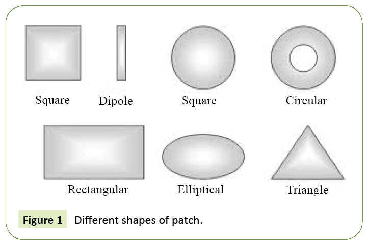
Major requirements of antennas in today’s wireless communication systems should have good performance parameters in terms of return loss, bandwidth, gain, radiation pattern, antenna efficiency. Micro strip patch antennas fulfill all these requirements [1]. Along with these advantages, these antennas also suffers from so many disadvantages including low gain, narrow bandwidth, low efficiency, low power handling capacity, surface wave excitation [2]. These limitations make the performance of micro strip antennas poor. A micro strip antenna consists of three layers; one is a radiating patch, a dielectric substrate and a ground plane on the other side. Radiating elements and feed lines are photo etched on the dielectric substrate (Figure 1) [3].
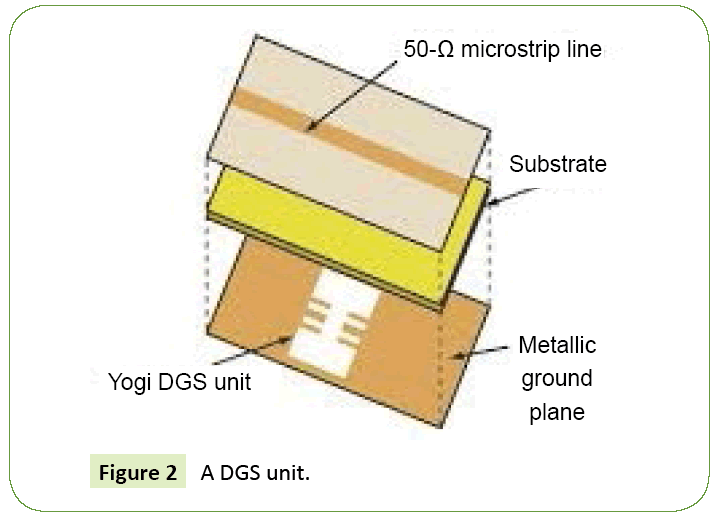
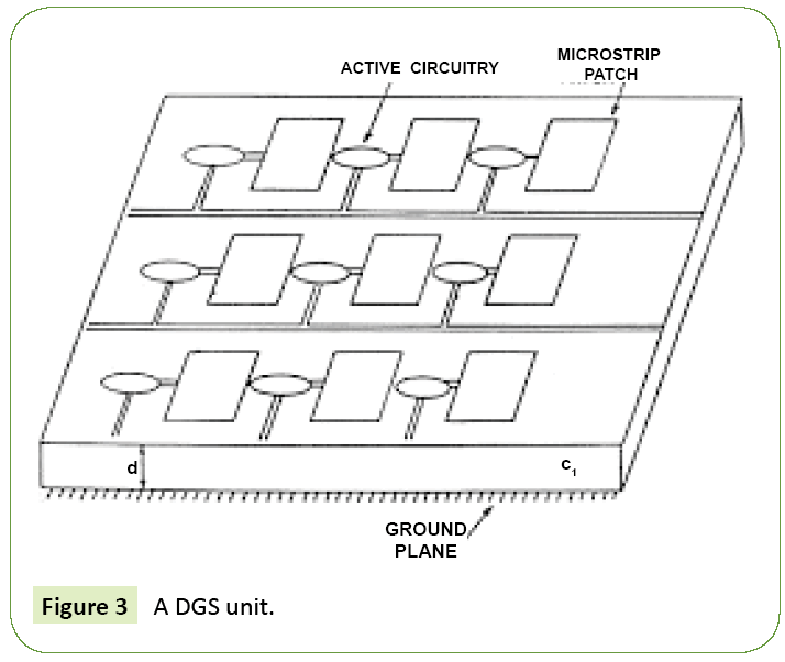
Patch may be of any shape like square, rectangular, circular, elliptical, triangular or any other configuration. But configurations which are mostly used are rectangular and circular [4]. Antenna array is combination of individual antennas together [5]. They can providecular. This is because of their small size as compared with other shapes. One of the techniques which are used to improve the performance of Microstrip patch antenna is using antenna array [6]. Antenna array is just collection of individual the capability of a steerable beam (radiation direction change) as in smart antennas. They can provide a high antenna gain by using simple antenna elements. It provides a diversity gain in multipath signal reception. They enable array signal processing and overcome the disadvantages of patch antennas [7]. It enhances the performance of patch antenna [1,8]. Further improvement in results can be done by applying defects in ground plane. This is realized by etching off simple shape from the ground plane. These structures are used to make the antenna size small and good performance in wireless communication. These defects can be of any shape and size. These can be placed anywhere in the ground plane. For better results, its geometry can be chosen from simple to complex as discussed in to reduce mutual coupling. There is no need of large area for its implementation [2,9]. DGS have relocated frequency which makes antenna small. It also reduces the mutual coupling in antenna arrays (Figures 2-4).
Antenna design
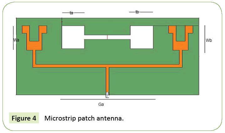
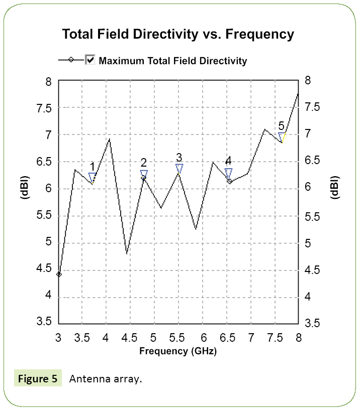
A proposed micro-strip patch antenna array is shown in Figure 5. The proposed antenna array consists on a single substrate [10]. The antenna design is made on a FR4 substrate having dielectric constant of 4.4 and height of the dielectric substrate is chosen as 1.5 mm. 50 Ω micro-strip feed lines are used to feed the radiating patch [11]. The dimensions of antenna are selected such that it should have good performance in terms of return loss, directivity and gain. A novel design of micro-strip patch antenna array of 2 × 1 is designed. Antenna array is mainly used to improve the antenna parameters [12]. In the proposed antenna array, all the designing parameters are selected based on transmission line mode. Using the dimensional equations, the dimensions of the this antennas are the length of the ground plane Lg is 120 mm, width of the ground plane Wg is 50 mm. Length of the feed Lf is 9 mm and width of the feed Wf is 2 mm. antenna is simulated using the Electromagnetic simulator, IE3D. By using these dimensions a single micro-strip patch antenna is designed [13]. By using T-power divider circuit micro-strip patch antenna array with same dimensions is designed on a same substrate. Microstrip patch antenna array is designed to increase the gain [14]. The array antenna consists of two single patches on the same substrate. In this array antenna the gap between the antennas is 80 mm (Table 1; Figures 4 and 5).
| Parameters | Value(mm) |
|---|---|
| Lg | 120 |
| Wg | 50 |
| Lp | 16 |
| Wp | 16 |
| Lf | 2 |
| Wf | 9 |
| W1, W2 | 5 |
| W3,W4 | 11 |
| L1,L2 | 5 |
| L3 | 10 |
| Ga | 80 |
| Wa, Wb | 15 |
| La, Lb | 15 |
Table 1: Dimensions of micro–strip patch antenna array.
For further improvement in performance of antenna, a new geometry of DGS is used. Length of DGS La, Lb is used. Width of DGS Wa, Wb is used. An improved structure of DGS is applying on an antenna array enhances the overall performance of an antenna. Simulated results of the antenna array are discussed below. Geometry of DGS can be of any shape [15].
Simulated results
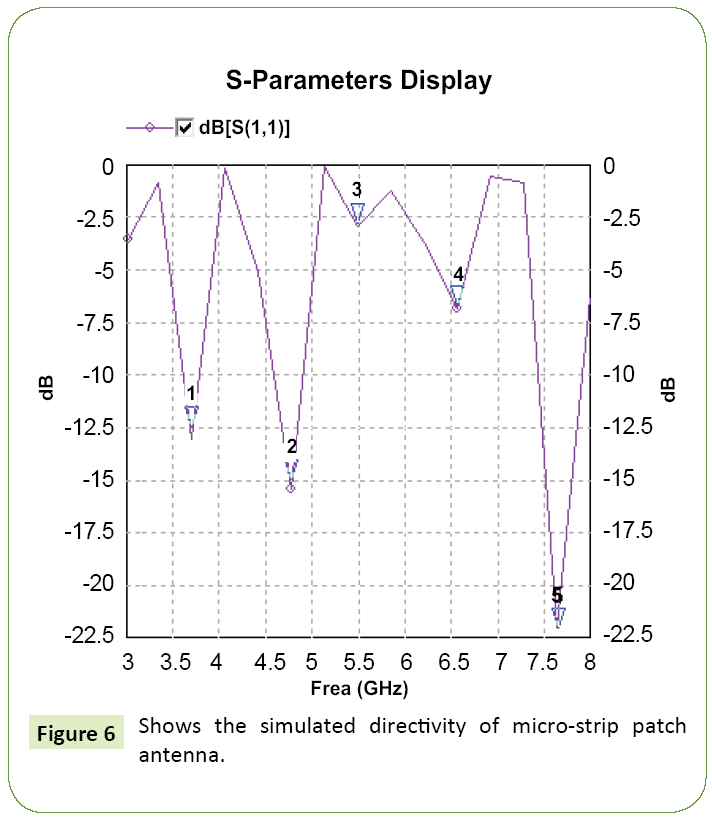
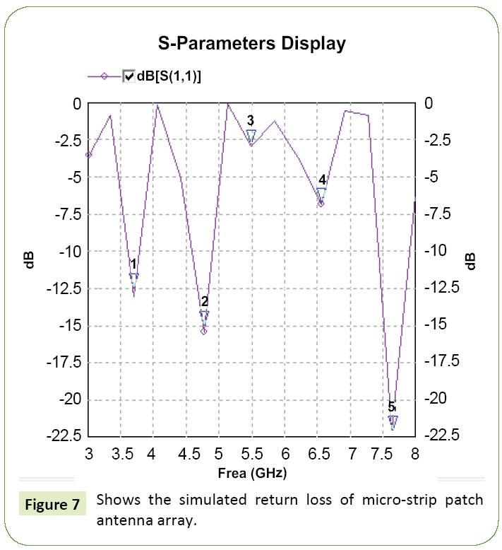
In this work, simulations results of return loss, directivity and gain of the designed antenna array are measured and presented (Figure 6) [16]. This design shows value of the directivity 6.827 at frequency of 7.642 (Figure 7).
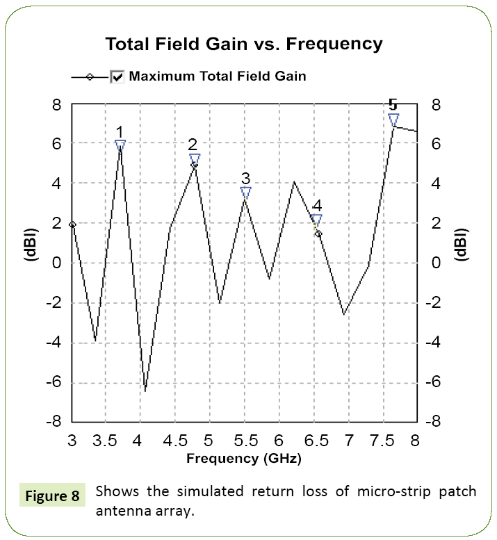
Return loss is -21.993 at the frequency of 7.642 that will be applicable for ISM band applications (Figure 8 and Table 2) [17].
| Parameters | Frequency | Value |
|---|---|---|
| Directivity | 7.642 | 6.827 |
| Gain | 7.642 | 6.774 |
| Return loss | 7.642 | -21.993 |
Table 2: Results.
Conclusion
In wireless communication system, important Antenna requirements are including low cost, small size, directivity, high efficiency characteristics and easily integration. By this review, it is described that patch antenna satisfy all of these requirements. Because of good nature of micro strip patch antenna array (MPAA) as compared to micro strip patch antenna (MPA), it should enhance the resulting parameters in terms of bandwidth, return loss, beam width, radiation pattern, directivity, pattern, return loss, directivity and efficiency. In addition, by using defected ground structure the size of an antenna become small. It also reduces the mutual coupling. DGS micro strip array antenna should collectively improve the overall performance of an antenna.
References
- Garg R, Bhartia P, Bahl IJ, Ittipiboon Micro stripAntenna Design Handbook. Artech House, Boston, London.
- P-S Kildal (2000) Foundations of Antennas: A Unified approach. Student litteratur p: 394.
- Milligan TA (1985) Modern Antenna Design. (1st edn), McGraw-Hill p: 408.
- Stutzman WL, Thiele GA (1981) Antenna Theory and Design. (1st edn), Wiley p: 598.
- Saunders SR (1999) Antennas and Propagation for Wireless Communication Systems. (1st edn), Wiley, p: 409.
- Harish A, Sachidananda M (2007) Antennas and Wave Propagation. Oxford p: 402.
- Shackelford AK, Kai-Fong L, Luks KM (2003) Design of Small-Size Wide-Bandwidth Micro strip-Patch Antennas. IEEE Antennas and Propagation Magazine.
- Mosallaeiand H, Sarabandi K (2004) Antenna Miniaturization and Band width Enhancement Using a Reactive Impedance Substrate. IEEE Transactions on Antennas and Propagation.
- Rahmat-Samii Y, Kona KS, Manteghil M, Yueh S, Wilso WJ, et al. (2006) A Novel Lightweight Dual-Frequency Dual-Polarized Sixteen-Element Stacked Patch Micro strip Array Antenna for Soil-Moisture and Sea-Surface-Salinity Missions. IEEE Antennas and Propagation Magazine.
- Hallbjörner P, Skarin I, From K, Rydberg A (2007) Circularly Polarized Traveling-Wave Array Antenna with Novel Micro strip Patch Element. IEEE Antennas and Wireless Propagation letters.
- Haiwen Liu, Zhengfan Li, Sun X, Junfa M(2005)Harmonic Suppression with Photonic Band gap and Defected Ground Structure for a Micro strip Patch Antenna. IEEE Microwave and wireless components letters pp: 1531-1309.
- Guha D, Kumar C, Pal S (2009) Improved Cross-Polarization Characteristics of Circular Micro strip Antenna Employing Arc-Shaped Defected Ground Structure (DGS). IEEE Antennas and Wireless Propagation letters.
- Iriarte JC, Ederra I, Gonzalo R, Brand Y, Fourmault A, et al. (2009) EBG Superstrate Array Configuration for the WAAS Space Segment. IEEE Transactions on Antennas and Propagation.
- Oulombe MC, Caloz SFKC (2010) Compact Elongated Mushroom (EM)-EBG Structure for Enhancement of Patch Antenna ArrayPerformances. IEEE Transactions on Antennas and Propagation.
- Nashaat D, Elsadek HA, Abdallah EA, Iskanderand MF, El Hennawy HM (2011) Ultra wide Bandwidth 2x2 Micro strip Patch Array Antenna Using Electromagnetic Band-Gap Structure (EBG). IEEE Transactions on Antennas and Propagation, pp: 0018-926X.
- Liang B, Sanz-Izquierdo B, Parker EA, Batchelor JC (2015) A Frequency and Polarization Reconfigurable Circularly Polarized Antenna Using Active EBG Structure for Satellite Navigation. IEEE Transactions on Antennas and Propagation pp: 0018-926X.
- Dissanayake T, Esselle KP (2008) UWB Performance of Compact L-shaped Wide Slot Antennas. IEEE Transactions on Antennas and Propagation.
Open Access Journals
- Aquaculture & Veterinary Science
- Chemistry & Chemical Sciences
- Clinical Sciences
- Engineering
- General Science
- Genetics & Molecular Biology
- Health Care & Nursing
- Immunology & Microbiology
- Materials Science
- Mathematics & Physics
- Medical Sciences
- Neurology & Psychiatry
- Oncology & Cancer Science
- Pharmaceutical Sciences
