Key words
Injection, Spray, Injector, Injector plate, Combustion chamber, liquid missile
Introduction
The function of the liquid fuel missiles engines is very depended on injection characteristics that are produced by
injectors. The method of fuel injection in to the combustion chambers in combustion process is very important.
Because of the complexity and unknowing of the spray atomization, the most of researches have been done for
experimental in this case. This process is very Obscurant and its mechanism is not so clear because some of droplets
are break up and joint again. Therefore, the droplets with different sizes produce in this system that they are
depended on the initial pressure and temperature of interior of the combustion and evaporating the droplets too [1,2].
One of the important steps in fluid powdering or atomizing and presenting different break–up models is inspection
of spraying process with experimental and analytical methods. Producing and providing fuel mixture that is
including of oxidizer or Reducer affects
Accessories of laboratories models
The laboratories models that are used in this investigation includes: injector, injector plates and combustion chamber
that are explained below.
Injector is a mechanism for converting the fluid into droplets and spraying them to the combustion chamber. The
faster impinging the droplets, the faster evaporating the fluid atoms therefore the efficiency of combustion is higher
and increases trust force [3,4]. Figure (1) illustrates the using of the centrifugal injector two–pedestals blending.
Combustion chamber model, experimental and numerical injection parameters from viewpoint of macroscopically
and microscopically are scrutinized. In this case, due to advantage and vast usage of centrifugal injectors and
because of distribution and more desirable uniformly injection in circular injector plate which in previous researches
are done, have been used. To validate the injection process and spray characteristics which are measured in Cold-
Test and PDA laboratories, the results are compared with numerical modeling and previous researches. Combustion
chamber model, experimental and numerical injection parameters from viewpoint of macroscopically and
microscopically are scrutinized. In this case, due to advantage and vast usage of centrifugal injectors and because of
distribution and more desirable uniformly injection in circular injector plate which in previous researches are done,
have been used. To validate the injection process and spray characteristics which are measured in Cold-Test and
PDA laboratories, the results are compared with numerical modeling and previous researches [5,6].
Figure 1 Centrifugal injector made of brass (includes: external injector, cap, internal injector and brazed injector)
The arrangement of injectors on the injector plate is very important. The manner of arrangement them on the injector
plate in type conical of spraying and impinging jet fluids is effective. Figure (2) is the scheme of the circular injector
plate that is used in this project (swirled atomizer).
Figure 2 Internal and external scheme of the circular injector plate
The model of missiles micro motor with liquid fuel that is made for this project is similar to actual motors RD–105
and RD–106. For computing of the combustion chamber cross section, the computations of injector plates are being
used that are diameter of combustion chamber cross section. The value of injector plate or combustion chamber
diameter is equal to 15 cm. Figure (3) shows micro mortar’s dimensions.
Figure 3: Laboratory combustion chamber dimensions
Laboratory experimental tests
These tests are accomplished in two cold – test and PDA laboratories. Cold – test mechanism includes: Under
pressure fluid container, Nitrogen bottle 40–liter, 150–Atmosphere pressure, manometer and regulator for regulating
associate pressure, pressure indicator for entering differential pressure on two sides of injector plate, camera with
fast graphing (1000 frames on per second and 8-megapixel resolution), radial and sectional collectors for
scrutinizing uniform injection and measuring distribution on two directions r–θ.
The PDA laboratory is used for measuring the velocity and diameters of droplets that are sprayed, is shown in figure
(4) on collection mechanism.
Figure 4 PDA measuring mechanism
The injector is usually tested by water in injection laboratory. The fluid specifications in the calculations is water
specification should be used in laboratory environment temperature.
In general, the use of oxidizer or reducer for testing of the injector plate and injection process in high pressure is
very dangerous and on the other hand is impossible often, these are self–flammable therefore test of injection and
spraying is usually done with water fluid. The alternative fluid should be similar to thermo physic condition of real
fuel.
The most effective parameter that affect on injection process is kinetic viscosity. For application of laboratory fluid
with real fluid oxidizer or reducer the equation 1 is used [1], [7].
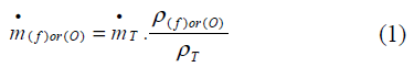
Where, T is fluid index that is tested.
Materials and Methods
The experimental tests are used for investing of the injection parameters includes cold–test and PDA mechanisms.
Results of cold–test injection include:
Flow-pressure test
This test is done for flow of the injectors on different high pressures. Flow–pressure rates in centrifugal injectors are
shown on figure (5).
Figure 5: Changes of injector flow to differential pressure
Uniform injection test
The injectors were tested in uniform injection on 4 bars and l0 bars. And also, 6 bars and 8 bars nominal pressure. In
paying attention with water volumes in collector’s combustion the spray distribution diagram is plotted.
Figure 6: Distribution of injection flow on sample injector in θ direction
Angle of spray test
The goal of this test is scrutinizing the effect of differential pressure on two injector heads on properties of injection
and break–up spray jet. One type of oxidizer injector and one type of reducer injector are being tested and angle of
spraying in a conic shape is measured and scanned. This test is done for observation of introducing conic shape
spraying from contact of injectors on injector plate. The angle of spray in internal and external is 80 and 70 degrees.
Figure 7: Angle of spray in internal (L) and External (R) injectors
Figure 8: Tested injectors on injector plate in Pf = 10(bars), Po =4 (bars)
Testing the flow distribution in collectors
This test is accomplished for output of injector plate pressure. The graph of flow–injector plate pressure is shown in figure 9.
Figure 9: Distribution of flow in two sprays of injector plate
Investigation of injection parameters by PDA
After calibration and provision of the system, changes its displacement into two directions x, y from canter to radius
of conic spray with defined steps. The average of 1500 points is calculated in each of steps. The system displaces in 17 stations on each test of injector on defined pressure. In other words the droplet compressibility in conic spray and
density of injection are increased through the power of the laser ray because it is decreased by contacting and
passing the droplets around the measuring area. To determine the spray diameter and its velocity are invested by this
mechanism [8]. The results of this test is shown below for oxidizer on pressure range Po= 4-6 bars and reducer Pf=
8-10 bars ranges.
Table 1: Results of PDA test for Po= 6 bars and Pf= 8bars
The results for mean diameter, Sutter diameter and velocity of atoms are shown below.
Figure 10: The mean diameter and particles SMD for Po=6 bars and Pf=8bars
Figure 11: The mean diameter and particles SMD for Po=4 bars and Pf=10 bars
Flow simulation
Flow simulation is accomplished by CFD that proper physical and Mathematical models and optimum strategy is
required. GAMBIT software by means of under-order is used for simulation and analyzing [9].
• Geometrical modeling (by means of the GAMBIT software)
• Spreading of calculation range
• Determining of materials properties
• Determining of proper initial conditions
• Investigation and Analyzing the method (Methodological)
• Inspection the results
• Saving the results.
Geometric modeling and meshing the combustion chamber
Modeling and designing the combustion chamber is shown below.
Figure 12: Circular injector plate and injectors arrangement (R), combustion chamber dimension model (L)
Figure 13: Meshing the combustion chamber with structural grid solver
Selection for flow solution
One of the numerical solution methods is selected by FLUENT software.
• pressure–base solver
• Density-base solver
Generally the pressure–base solver is used for uncompressed flows while the density-base solver is used for
compressed flows with high velocity. Both of these methods are reformulated and progressed for solving the flow
conditions.
Control volume technique is being used for solving that includes:
• Division of solving range to independent control volume with calculated meshing.
• Integration from independent equations on control volume for algebraic equation with inconsequent independent
variables. (I.e. velocities, pressure, temperature and conservation quantities)
• Linearizing discrete equations and solving linear equation system to gain new value for independent variables.
Figure 14: Pressure–base solver algorithm diagrams for two states, Independent and coupled
Here, the pressure–based solver couple algorithm is being used. This procedure is a usual method and forecasting
the results. Velocity field is gained by solving the pressure equations (corrected pressure equations). The pressure
equation is received from continuity and momentum equations, too. So that velocity is corrected by pressure
equation and satisfies the continuity equation. Whereas these equations are non–linear and coupled, solving process
is continuing until the converging is appeared [10].
Turbulence model selection
Improvement of k-ε models in different turbulence models is used for turbulence flows and improves below [11]:
• Realizable k-ε model includes new formulation for turbulent viscosity.
• A new transition equation for losing rate (ε) is used.
• This method has high accuracy in forecasting spray rates in planar and circular jets.
• Excellent operation in swirled flow, boundary layers under reversal pressure gradients, flow separation and
circular flows.
Boundary layer conditions
Preplanning with different types of boundary conditions is accomplished by these theories [12]:
• Reflect boundary condition for walls, symmetrical flows and axial boundaries with reactionary coefficients.
• Escaped boundary condition for all of the flow bounds (i.e. boundaries with pressure or velocity inputs, output
boundary condition in pressure …)
• Internal boundary conditions for internal boundaries (I. e. Radiators and porous spray).
Equations of motion
The fluent software solves conservation of mass equations and momentum for all of the flows. The conservation of
energy equation is added to compress and conduction flows, too. The conservation of energy equations for chemical
mixtures should be solved in a different manner. Transient turbulent equations are required for turbulent flows. In
this article the conservation equations for laminar flows are determined in inertia reference [13].
• Conservation of mass equation
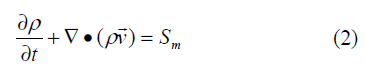
This equation is continuity equation in general form and properly for compressible and uncompressible flows.
Source term(Sm) is added mass to continuity phase from the second non continuity phase (Because of evaporation of
fluid droplets) and the other terms must be added by the user.
• Conservation of momentum equation
This equation in the inertia reference is:
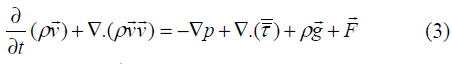
P: static pressure, τ: tension tensor,  external forces (due to interaction with non-continuous phase) and
body gravity.
external forces (due to interaction with non-continuous phase) and
body gravity.  : Vector is dependent models (I. e. Porous environments and identified terms by user). The tension
tensor is
: Vector is dependent models (I. e. Porous environments and identified terms by user). The tension
tensor is
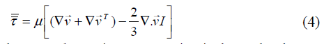
μ: viscosity, I: unit tensor and the second term in R.H equation is thermal volume expansion.
• Energy equation
The general form of energy equation is:

Keff: effective conduction coefficient (k+ kt is based on turbulence model that kt is turbulent conduction thermal
coefficient.) and  : is flux influence of materials. Three terms of right sight of the equation are energy transition for
conduction, influence and viscosity losses, respectively. Sh: includes chemical thermal and each thermal resource.
: is flux influence of materials. Three terms of right sight of the equation are energy transition for
conduction, influence and viscosity losses, respectively. Sh: includes chemical thermal and each thermal resource.
• Transition equations in Multi–Phase of different chemical flows
Multi–phase flows are used in transition equations solving conservation equations in multi–phase flows, forecasting
Convection–Diffusion equation for k-term and each local mass( Yki ). The general equation and extended
conservative chemical types is:
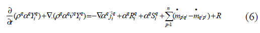
Rqi is net producing rate for sympathetic types by chemical reaction q–phase,  is the source of mass transition
between i and j for q to p phase and R is incongruous reaction rate.
is the source of mass transition
between i and j for q to p phase and R is incongruous reaction rate.  : is volume fraction for q- phase and Sqi producing rate by no continuity phase with each other resources defined by the user.
Conclusion of numerical modeling
After modeling the injector plate and arrangement of oxidizer and reducer injectors with solid work software,
designing and meshing the combustion chamber are recalling by Gambit and Fluent software. Flow simulation with
desired solver, boundary conditions fluid properties, turbulence model, checking mesh and …, is iterated with
convergence criterion  . Amounts of flow of injectors, differential pressure on two sides of injector and
angles of spraying are entry values in this simulation. At first, the flow simulation is done for one injector and the
gained results compared with experimental amounts and previous investigations then after trusting on outputs,
simulate for all of the injectors.
. Amounts of flow of injectors, differential pressure on two sides of injector and
angles of spraying are entry values in this simulation. At first, the flow simulation is done for one injector and the
gained results compared with experimental amounts and previous investigations then after trusting on outputs,
simulate for all of the injectors.
The below selected figures illustrate the simulation process from geometrical production to gained results:
Figure 15: Arrangement and meshing Injectors in combustion chamber model
Figure 16 The velocity and spraying Profiles in the middle injector
Figure 17 Counter of velocity magnitude for spraying on one injector
Figure 18 Counter of velocity for spraying on top of the injector
Figure 19 Changing droplets velocity on the time
Figure 20: The spraying profile resulting contact of two sprays
Figure 21: All of the sprays profile before the sprays contacts
Figure 22: The spray contact profile after complete convergence
Figure 23: The spraying profile in the combustion chamber after complete convergence
Figure 24: The counter of velocity for the linear injectors on the injector plate
Figure 25: The complete expanded of the sprays in combustion chamber
Figure 26 Graph of changing velocity on y-axis ( mean V )
Figure 27: Graph of changing particle diameter by time
Investigation and comparing the experimental and simulation results
In this section, the numerical results are compared with experimental results. Also, confirming the recent results and
revolving accuracy are compared with previous investigations, Amount of droplets velocity is compared on two
states ({pf = 10 bars , po = 4 bars } , { pf = 8 bars , po = 6bars}) are shown in figure 28 and 29.
Figure 28: Comparing PDA results with numeric results for { pf = 8 bars , po = 6bars}
Figure 29: Comparing PDA results with numeric results for {pf = 10 bars, po = 4 bars}
Table (2) shows amounts of the mean diameter, Sutter diameter and droplet velocity are gaining from experimental
and numerical methods.
Table 2: Comparing velocity and diameter in experimental and numerical solutions
In this research, authenticating and confirming the results are compared with Vessalo p. and Ashgriz N.([14] and
[15]) results that, They use laser measuring instruments (PDA), which is accomplished by Atlantic researching
Institute for (22–N) trust in real missile engine is done.
Also, in their research, water is operating fluid in these tests (oxidizer and reducer). The centrifugal injector is used
in this test. This figure shows comparing velocity contour with the recent results.
Figure 30: Compared velocity counter for an injector with Vessalo . p. results
Results and Discussion
By means of gained tables and figures, we can find out:
• The gained numerical results from internal and external injector velocity by the time were graphed in figure 16 to 20. As you see, the droplets velocity with experimental results decreased by the time while the distance of injector
increases and misses the initial momentum droplets.
• Figure 22 to figure 26 illustrate distribution and contact of spray to all of the injectors on the injector plates in
combustion chamber. These figure show injectors spray from the beginning to convergence results.
• Figure 26 shows droplets velocity in injection spray. At first step as the droplets velocity decreases while
decreasing momentum, then increases suddenly after contacting with injection spray to the other spraying injectors
and this procedure repeat as decreasing.
• Figure 20 and 27 droplets diameter counter and graph are shown for one injector the farther injector nozzle, more
decreasing particles diameters.
• Figure 28, 29 and table (2) indicates droplets velocity, mean diameter and Sutter diameter illustrated in two
injection pressure ranges (({pf=10 bars, po=4bars}, { pf = 8 bars , po = 6bars}). These results are scrutinized and
similar to decreased droplets velocity and droplets mean diameter.
• Figure 30 shows comparing Vessalo and Ashgriz results that the distribution of injector spray is symmetric and
velocity profile is gained perfectly, The farther nozzle in axis direction, the more decreasing droplets velocity.
Acknowledgment
We devoting from precious professor his Excellency doctor Ommi F. for it is unsparing guidance in improving and
accomplishing this research. Special thanks to Excellency Mr. Farajpour Eng. in improving this project. Also Mr.
Taheri M .that helps us in laboratorial experiment operations greatly.
References
- G.P Sutton, 1986, John Wiley and Sons, Inc, New York.
- E Giffen, A Muraszew, 1953, Chapman and Hall.
- R.D Reitz, F.V Bracco, Book Chapter The Encyclopedia of Fluid Mechanics, Houston, Texas, 2005,Vol. 3, Chapter 10, pp. 233-249.
- H Liu, 2000, Science and Engineering of Droplets, New York U.S.A.
- M.R.O Panao, A.L.N Moreira, 2005, Instituto Superior Te´cnico, Lisbon, Portugal.
- P Maniarasan, J. R Padenb, M.T Nicholas, 2008, College of Engineering and Technology, India 3 February.
- C Baumgarten, 2005, Internal Combustion Engines, Springer, Hannover, October.
- Z Wu, Z Zhu, Z Huang, 2005, School of Mechanical Engineering, Shanghai, December.
- D Rolf. C Reitz, 1996, Mechanical Engineering Department University of Wisconsin, May 7.
- K. R Babu, M Vnarayanaswmy, 1982, (The 2nd Int. Conference on Liquid Atomization and Spray System, June).
- Q Liu, S.E Cooper, Q.I Lijun, Z Fu, 2006, College of Engineering and technology, Wuhan, Hubei, China. August.
- M.F Heidmann, R.J Priem, J.C Humphery, 1922, NACA TN 3835.
- A.P Vasiliov, B.M Koderaftsov, B.D Korbatinkov, A.M Ablintsky, B.M Polyayov, B.Y Palvian,1993 Principles of Theory and Calculations of Liquid Fuel Jet, Moscow.
- R.D Ingebo, 2002, NACA TN 4222.
- P Vessalo, N Ashgriz, 2005, Journal of Propulsion and Power.